Lab Report 1
Breadboards: To my understanding, a breadboard is used for temporary electronic prototype designs and allows for the creation of a test circuit without soldering.
Video on how I completed Lab #1
Multimeter: When you have a circuit that doesn’t seem to work, a multimeter will allow you to test where the current is running through, and not running through. It can test other people’s work to understand their circuits, and even test a battery’s volts.
Final Projects Views: Tia’s- I liked how she took something that we use everyday, such as a guitar pedal, and didn’t even have to reinvent it, was just able overall to understand the basics of it, and represent it. (Plus, she used it in her original songs, which I think is so cool). Jaye’s- I felt as though her final was really interesting and fun. I never really realized all the possibilities that can come out of breadboards, and wires, and essentially all the parts we bought for the class. I liked how she mended a few different ideas, such as a tremolo with a vocoder in harmonies. Connor’s- I really liked how he was somehow able to connect his phone to the breadboard, and almost EQ and edit/ engineer the song automatically. I really want to look into how to do that.
Lab Report 2
Lab Report 3
1a) The first thing you do when prepping your soldering tool is turning it on. You set the temperature knob between 4 and 5 (depending on the model the should be the “sweet spot” to get it hot enough to start working). The way you prep the tip of the soldering iron is by grabbing a damp sponge and wiping away the excess rubber or solder from the previous user that was dried up on the tip. To see if it’s hot enough, you take some solder wire and touch it to the tip, if it smokes, you’re ready.
1b) Before you step away from the soldering iron, you should clean it off, by pressing the tip amongst the damp sponges and then place it back in the holder. You always want to make sure you don’t leave it on any plain surface because the iron can/will most likely burn through it. ALSO, don’t just hand the iron over to the next person, because who knows… you can drop it… or in handing it off someone can burn a finger.. or a hand or something. SO just put it back in the stand/holder it comes with.
2a) Make sure you’re plugged into the right spot on the multimeter. Your red cable should be plugged into the left if you’re measuring current, and right if you’re measuring volts.
2b) Power through a resistor: P=0.25W and V=9.25 V (Measured)
0.25/9.25= 0.027 A (27mA) which is my Current
9.25/0.027= 342.6 Ohms which is my resistance (This is the minimum resistance calculated)
Using a 470 Ohm resistor I measured 0.019 A (19mA)
470*0.019= 8.63 V (Calculated)
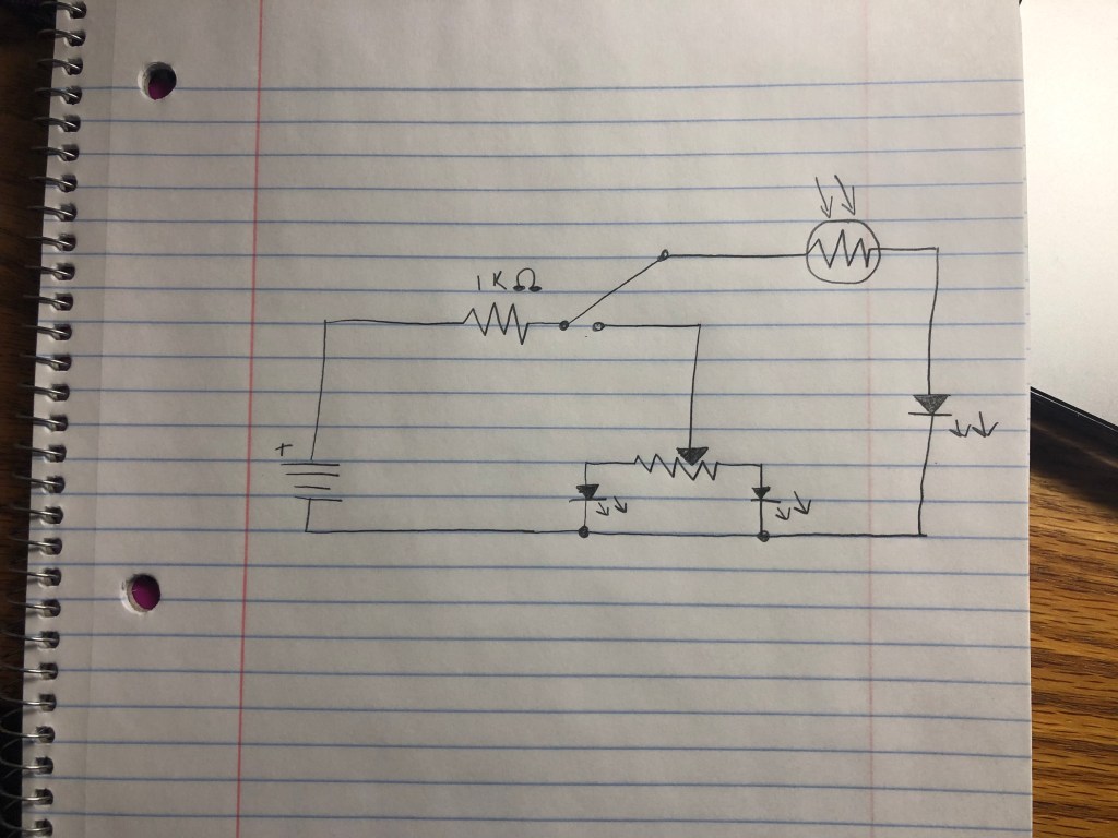
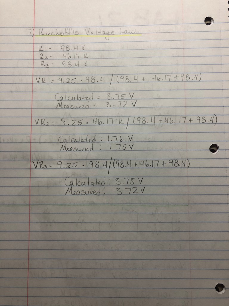
3) Kirchoff’s Current Law
Calculated Values:
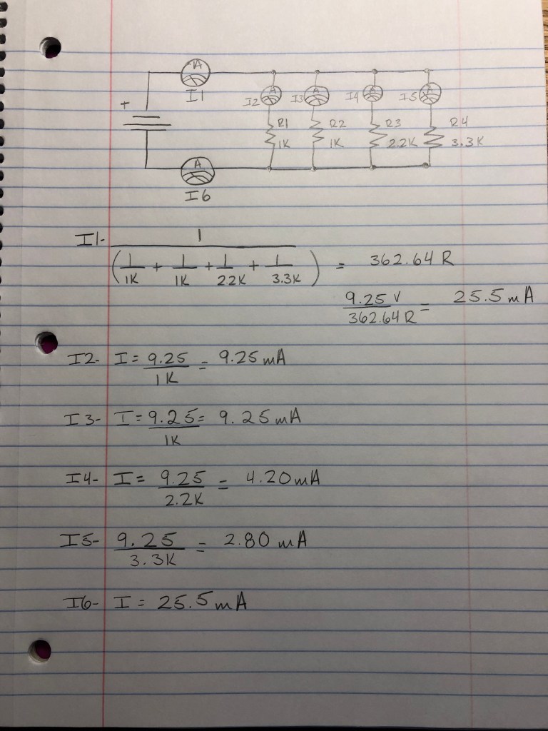
Measured Values were
I1= 25mA —– I2=9mA —– I3: 9mA —– I4: 4mA —– I5: 3 mA —– I6: 24 mA
Lab Report 4
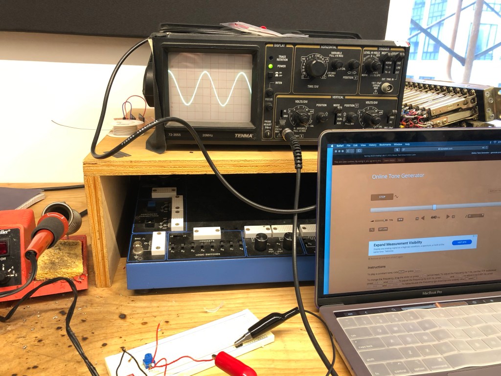
An oscilloscope’s primary function is to provide a graph of a signal’s voltage over time. The front panel of an oscilloscope is divided into three sections labeled vertical, horizontal, and trigger.
- Vertical: This is the amplification of the signal. Use the volts/div control to adjust the amplitude of the signal to the desired measurement range.
- Vertical controls are used to position and scale the waveform vertically
- Basically, the vertical position control allows you to move the waveform up and down so it’s exactly where you want it on the screen.
- Horizontal: This is the time base. Use the sec/div control to set the amount of time per division represented horizontally across the screen.
- These controls are used to position and scale the waveform horizontally.
- Trigger: This is the triggering of the oscilloscope. Use the trigger level to stabilize a repeating signal, or to trigger a single event.
THE MODE SWITCH
- Depending on your brand of oscilloscope, you will have a switch that switches the view on the screen from either channel one, channel two, or dual, which is both waves together.
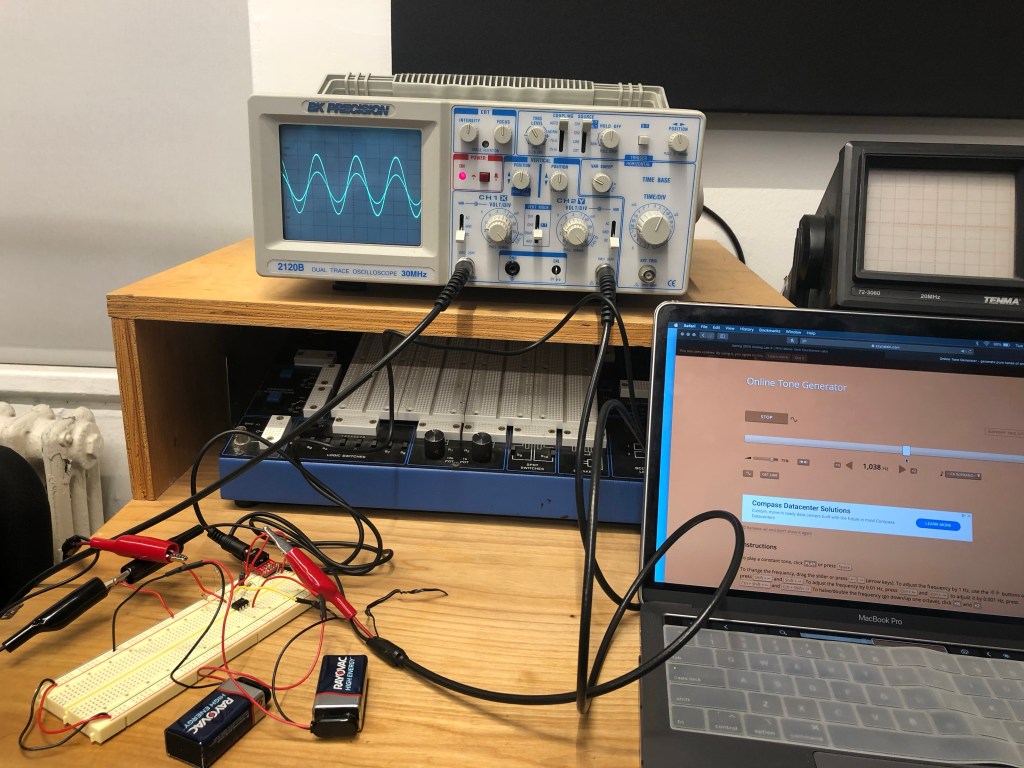
To even allow for a waveform to present itself on the screen, you would plug in some type of audio source, and play any waveform from any type of waveform simulation website, and then use the aforementioned sections and knobs to zero in on what you’re looking for.
Volts/Div and Time/Div
The volts-per-division setting (usually written as volts/div) is a scaling factor that varies the size of the waveform on the screen. If the volts/div setting is 5 volts, then each of the eight vertical divisions represents 5 volts. This refers to the Y axis.
The horizontal position control moves the waveform left and right to exactly where you want it on the screen. The time-per-division setting (usually written as sec/div) lets you select the rate at which the waveform is drawn across the screen (also known as the time base setting). If the setting is 1 ms, each horizontal division represents 1 ms. Changing the sec/div setting enables you to look at longer and shorter time intervals of the input signal. This refers to the X axis.
Trigger
This is essential for clear signal characterization. Trigger controls allow you to stabilize repetitive waveforms and capture single-shot waveforms. It can “freeze” the signal to show a clearer image.
Probe Connections
For probe connections, you go by the channels you have. For example, there were 2 channels allocated on the oscilloscopes we worked with, and both came with a black and red probe connected to a wire. The red probe went to the positive end, and the black was always connected to ground.
Turning the Pot
When you turn the pot, you see one of the two waves moving to its minimum and maximum amplitude. The maximum amplitude was 1 volt because we had the volts/div knob set to 0.5V, and at its lowest it would be 0v, which would be a flat line.
Lab Report 5
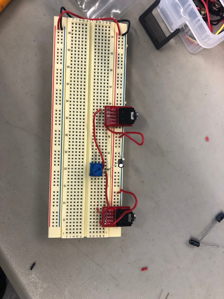
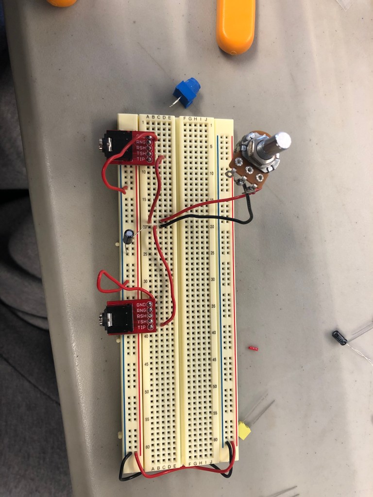
Part 2) DC blocking, current limiting circuit
Adding a resistor and capacitor on the inputs and outputs of your circuit is a good idea because it makes sure that a full 9V or 18 V or however many volts your battery has, is not being directly sent through your audio input (computer or phone), which would then short circuit your device.
4a) Noninverting Amplifier
Gain = (1 + R2/R1) so (1+10k/10k)
With a pot added: (1+0/10k) or (1+10k/10k)
Between 1 gain and 2 gain
4b) Inverting Amplifier
Gain = -(Rf/Rin) so -(22k/10k) = -2.2 gain
With a pot added: -(0/4.7k). = 0 or -(10k/4.7k) = -2.13
Between 0 and -2.13 gain

Lab Report 6
2a) C=1/(2π*10*20k)
C=1/(2π*10k*20) both are equal to 0.000000796 F or 0.796 uF
So, I used a 1uF Capacitor.
2b) Low pass filter
2c) C=1/(2π*10*20k)
C=1/(2π*10k*20) both are equal to 0.000000796 F or 0.796 uF
So, I used a 1uF Capacitor.
2d)
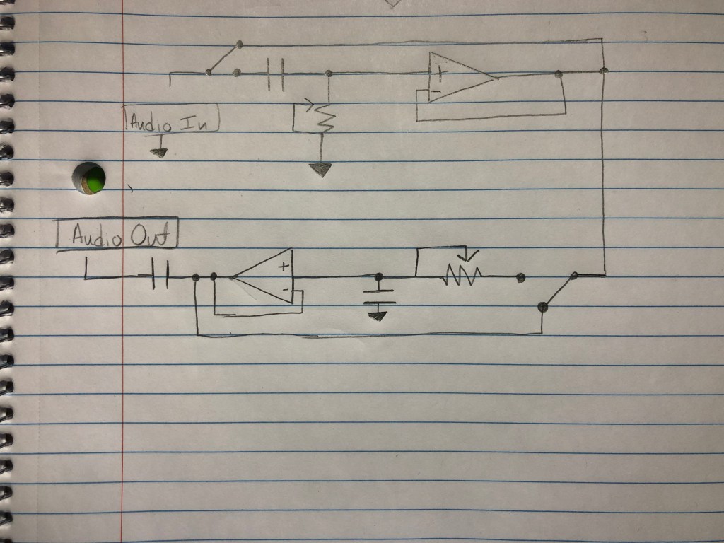
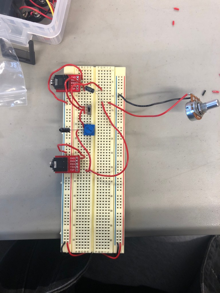
Part 3: Schematic
Part 4: You’ve made a 6db/octave filter. Say you want to make a 12db/octave filter. Or an 18db or 24db/octave filter? What do you do?
To increase the filter by +6db/octave, add another capacitor and resistor to the circuit.
Part 5:
A) I think I’m really interested in building either a Reverb pedal or truly, fully, challenging myself to construct a multi-channel processor. The multi channel processor stands out to me because it can fully change the song that is being input into the audio source. The reverb pedal interests me because, who doesn’t love a good reverb on a good mix?
B) Maybe my project would include a mixture of the both ideas. I might add a reverb knob to the processor.
C) A piece of analog audio equipment that I wish I could understand are pedals (mainly guitar). I wonder how it goes from the guitar, to the pedal, to the amp.
Lab Report 7
Oscillator
Oscillator with button
Lab Report 8
- With the oscillator we’re studying the comparator outputs a square wave and the integrator outputs a triangle wave.
- With an integrator, if Vin is positive the output voltage ramps down. If Vin is negative the output voltage ramps up.
- With a comparator, if the op amp’s + input is connected to a greater voltage that that connected to it’s – input, the op amp’s output will be about positive 9V DC. If the op amp’s + input is connected to a lower voltage that that connected to it’s – input, the op amp’s output will be about negative 9V DC.
- So the bigger the resistance R you use the slower the ramp gets, and the bigger the capacitor gets the slower the ramp gets.
- You would have to use a different resistor for each button so that the voltage going through that one specific button alone controls the speed of the ramp. By controlling the speed of the ramp, that controls the speed of the square, so that ends up controlling the speed of the oscillator (frequency/pitch). In short, different resistance = different pitches.
Lab Report 9
- Symmetrical: A

2. Asymmetrical: B

3. No, the output of these two circuits will not sound the same or have the same volume because the second circuit has a buffer, and the first circuit does not. Without a buffer, the resistance of the speaker/headphones and the resistance of the diodes interact in a strange way, behaving as though they are in parallel, which can result in a significant decrease in volume, or some bizarre distortion effect that we do not want. However, with a buffer, we are able to avoid this through the nature of the feedback loop, which produces a strong output signal without the strange, undesired effects of the diodes’ resistance or a great volume decrease. To achieve this, plug the input signal into the positive input, and plug the output signal into the negative input. From here, it will be possible to properly hear and control the distortion effects. Overall, the distortion effects will sound correct with the buffer like in the second circuit, and the sound will be strange or very quiet without a buffer like in the first circuit.
4. With this circuit, if you turn the crossfader all the way to one side you’ll hear the original clean signal. If you turn the crossfader all the way to the other side you’ll hear distortion on the signal.
5. If you turn the potentiometer to its halfway point, you’ll hear the signal morph from one side to the other. You’ll hear the exact average of the two voltages of the two signals/sounds.
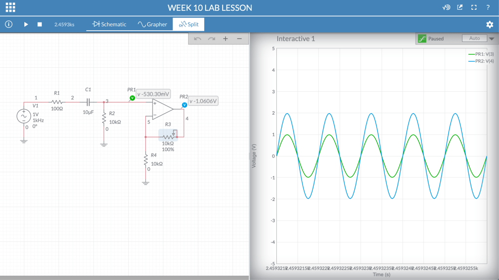
Lab Report 10
Link to Multisim Live: https://www.multisim.com/content/MEsehPkbqRBPLNAB9YDHUf/week-10-lab-lesson/open/
Lab Report 11
- I chose to focus on T-Rex, Dr. No Effects, and TC Electronics.
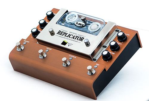
1a. T-rex: The Replicator Tape Echo guitar pedal replaced the size, weight, and inconvenience of an old tape echo machine with a new and improved version. I like the amount if options you have on this piece. For example,
- There are three output modes and a chorus mode that modulates the pitch of the echos.
- Two expression pedal inputs allow the player to control delay time and feedback in real time for instant synth-noise at your feet.
- It even has a real replaceable tape cartridge. This sets it aside from digital recordings because the analog use of a tape recording allows for the unpredictability of the recording, and the natural echo sound.
Dr. No Effects – The Skull Fuzz Pedal:
First of all, this guitar pedal is an actual model of a skull. That’s literally the coolest thing. AND THE EYE BALLS IN THE SKULL CONTROL THE VOLUME AND GAIN. Im sorry, but that’s so sick.
- This one comes with a gain or “fuzz” control knob, and a volume Knob.
- There’s a switch that allows for different variations in the “fuzz”
- What I dislike tho, is that I do think that there could’ve been maybe another effect added to this pedal, simply because it’s such a unique design, why not do something that only exists on this pedal? It seems like you really are just buying it for the look, and novelty of it.

TC Electronics:
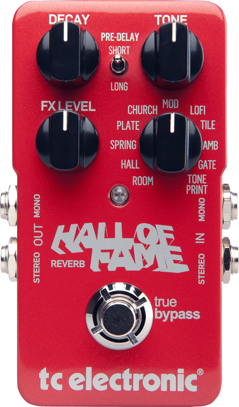
The Hall of Fame Reverb pedal has a really sleek all red classy look to it.
- This comes with a Delay, Tone, FX level, and Reverb Knob.
- I really like the fact that there are 10 options for reverb on this pedal. Ranging in from your typical “Church, hall” to then some that I’ve personally never seen which are “Tile” and “Gate”.
- What really sticks out to me, is that when I’m mixing and mastering a track (sound engineering wise), these terms are always common when your editing reverb and adding FX, so when I want to switch hats and go ahead and play guitar one day, I think it’s really cool that the terms are the same, and you know exactly the feel that you’re going to get.
- Something I dislike, is probably all of the words on the enclosure itself starts to get a little jumbled and the overall look of it kinda goes from sleek to cluttered.
1b. Overall, I think the differences from bigger companies and “boutique” companies is the open mindedness to taking risks. All of the bigger companies that I saw on the supplied website, had really simple designs, and models. Then you had a company like Dr. No Effects, where their pedal is a whole skull, or Danelectro’s Sitar Swami decorated to resemble an old hippie Volkswagen car.


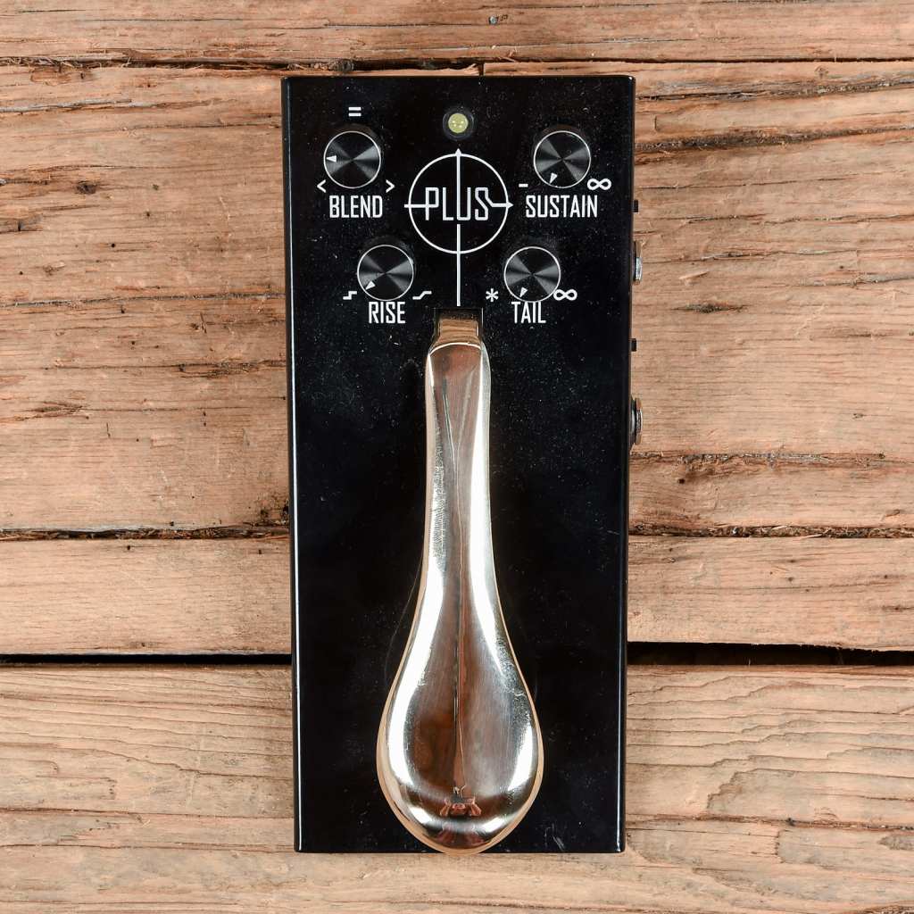
1c. Gamechanger Audio’s Plus Pedal sustainer provides a unique experience and sound that is undeniably different from any other pedal. This pedal has a piano sustain pedal attached to the top of it, and it allows for beautiful layering. You can strum one chord, hold the pedal down, and then go ahead an either solo or play melodies overtop as the pedal holds the original chord.
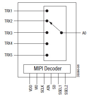
2. SP5T stands for single pole 5 throw, and it is a rotary switch. Similar to our 3 pin switches, there’s a middle pin, and then two terminals for it to switch to. The 5 throw gives an option of 5 terminals to switch.
3. Momentary switches are switches which only remain in their on state as long as they’re being actuated (pressed, held, magnetized, etc.). Most often momentary switches are best used for intermittent user-input cases; stuff like reset or keypad buttons. This is much like a joystick on a video/ arcade game.
A latching switch is a switch that maintains its state after being activated. A push-to-make, push-to-break switch would therefore be a latching switch – each time you actuate it, whichever state the switch is left in will persist until the switch is actuated again. Latching switches are used for lower risk applications and where it would be highly inconvenient for the operator to have to manually apply pressure to keep the switch on. It would be highly inappropriate to have to stand at a light switch to keep it switched on so a latching switch is far more suitable
Lab Report 12
- 2= 1.1*R*0.00001
- This gave me a resistance of about 182k Ohms
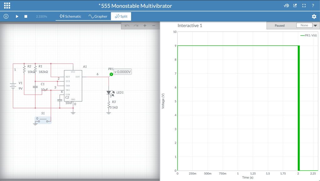
https://www.multisim.com/content/PjSrVwYnJyeZZn9WtqhWJ7/555-monostable-multivibrator/open/
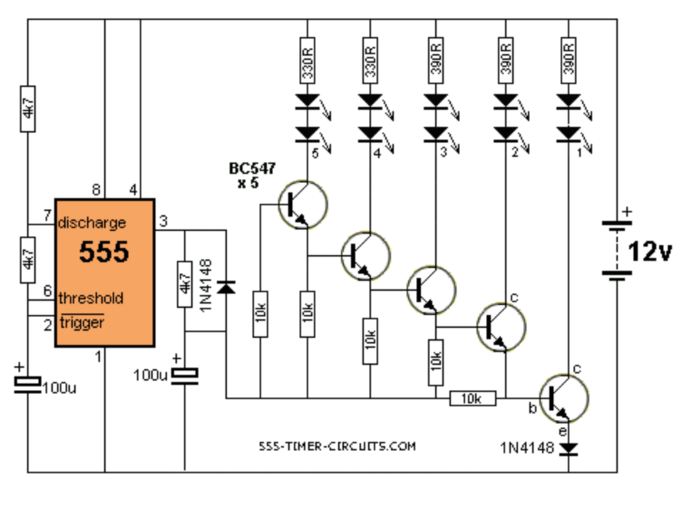
2. Additional Uses for 555 Timer: Bike Turning Signals
Two of these circuits are required on either side of the bike, or car, to allow the person to signal both of these directions. This circuit is an astable multivibrator, because the light blinks consistently on and off for a certain amount of time that is established by the values of R1 and the capacitor. It is very important for safety reasons that this is astable because when using it, the biker needs to be able to indicate which direction the bike is moving in for an indefinite amount of time, with the blinker consistently turning on and off, until they make the turn. When they make the turn, there should be away to turn the signal off (or if it were a car turn signal, it often automatically turns off after making the turn) so that the light stops blinking, until they need it to make another turn.
Lab Report 13
- Digital Projects Hall of Fame
- Nick Royall: I really enjoyed watching the video demo for this project. I though it was interesting how there were so many different “modes” from audio sequencers mode to midi keyboard mode. It really opened up all the possibilities for future projects.
- Lauren Schutz: I know that once we are in Digital lab we’ll get a better understanding of what we can possibly do with all the information and tools supplied, but I never thought that art such as paintings and breadboards could be combined. Lauren made a Touch-LED painting, where once you touched one of the flowers it lit up, and added color to the black and white painting.
- Dominic Yuan: I was extremely compelled by this project. The project was a Sound Reactive visualizer. Basically whenever anything was playing while hooked up to his device it would light up and change colors based on intensity of the music played.
2. Arduino: My google search was “Arduino Microphones” and this video was the first thing that popped up.
It shows how sound sensors can be used for a variety of things, one of them could be turning lights off and on by clapping. Here they used an Arduino to hook up the sound sensor to an array of LED lights which will beat with music, clapping or knocking. I though it was interesting to see how the “microphone” was able to pick up the sound of a song, or even a noise such as clapping and then automate an LED to go off. Definitely a project I would like to try in Digital.
3. Potentiometer: Analog
LED: Digital Output
Switch/Button: Digital
4. I have taken NYU’s Intro To Computer Programming for Non-Majors class where we focused on Python.
